For those of you unfamiliar with Citizens Broadband Radio Service (CBRS), the CBRS band is a newly-opened slice of spectrum from 3550 to 3700 MHz which can be used on a licensed (with priority) or unlicensed basis by organizations and enterprises in the U.S. Enterprises are looking to CBRS to quickly spin up private LTE/5G networks for new use cases that require interference-free spectrum and outdoor wide area coverage – think autonomous vehicles or handheld devices in a healthcare setting.
We’re excited about the technology and have partnered with Celona to deliver an innovative, turnkey solution to our customers. The initial technology used in the CBRS band is LTE, familiar in the cellular world but foreign to most enterprise engineers with Wi-Fi backgrounds. As an introduction, here are some of the concepts in CBRS technology.
Key CBRS concepts for Wi-Fi experts
1. Transmission symbols and OFDMA
CBRS uses the LTE OFDM waveform where multiple subcarriers are modulated independently across the band, in the same way as Wi-Fi, although the subcarrier spacing differs, at 15 kHz for CBRS against 78 kHz for Wi-Fi 6. The modulation schemes are also similar, with QPSK used for higher rates, and MIMO techniques multiply data rates where favorable multipath conditions exist.
2. Frame structure and TDD
However, the way transmissions are timed and controlled in CBRS is very different. Wi-Fi has traditionally used a packet-by-packet transmission scheme, where once a node has a transmit opportunity, it sends a full frame of data. A view of transmissions over time will show interleaved frames from different nodes. (Wi-Fi 6 has OFDMA options that are similar to CBRS, so an understanding of Wi-Fi 6 helps with CBRS.)
CBRS has a strong frame structure, where the base station transmissions define a frame every 10 msec, and client devices synchronize to that frame. The frame is divided into timeslots, where each timeslot is designated for downlink or uplink transmissions in an unchanging pattern. CBRS uses TDD (Time Division Duplex) and CBRS equipment can define a 50:50 or 60:40 split for downlink:uplink timeslots, with some time lost at the changeover.
3. Resource Elements and Resource Blocks
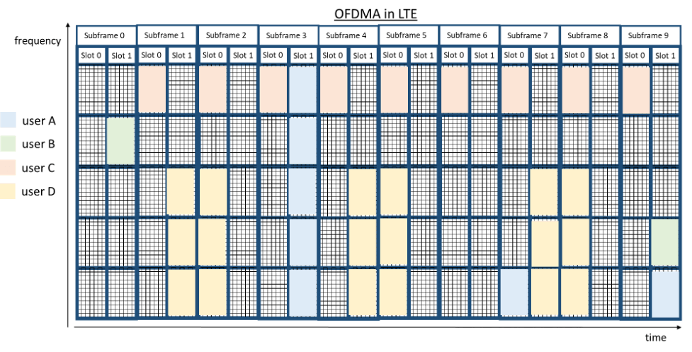
Because the CBRS frame is structured and predictable, each symbol interval can be identified and referenced by time and subcarrier coordinates. This allows engineers to construct a 2-dimensional grid showing every symbol, also called a Resource Element, in a frame. Since there can be 10,000 or more symbols in a wideband frame, they are grouped into PRBs (Physical Resource Blocks) for the purposes of allocating transmissions, where a PRB is 7 consecutive symbols across 12 contiguous subcarriers.
4. OFDMA and Resource Block allocation
PRBs are predefined in the frame structure, and designated for uplink or downlink, but the process of allocating each PRB to a particular transmitting node is called OFDMA (Orthogonal Frequency Division Multiple Access). This operates like the new OFDMA feature in Wi-Fi 6, but bear in mind that Wi-Fi allocates subcarriers within a packet duration, whereas CBRS uses PRBs in the frame structure. In both cases, the access point or base station exercises control over both uplink and downlink transmissions, which is a big difference from traditional Wi-Fi.
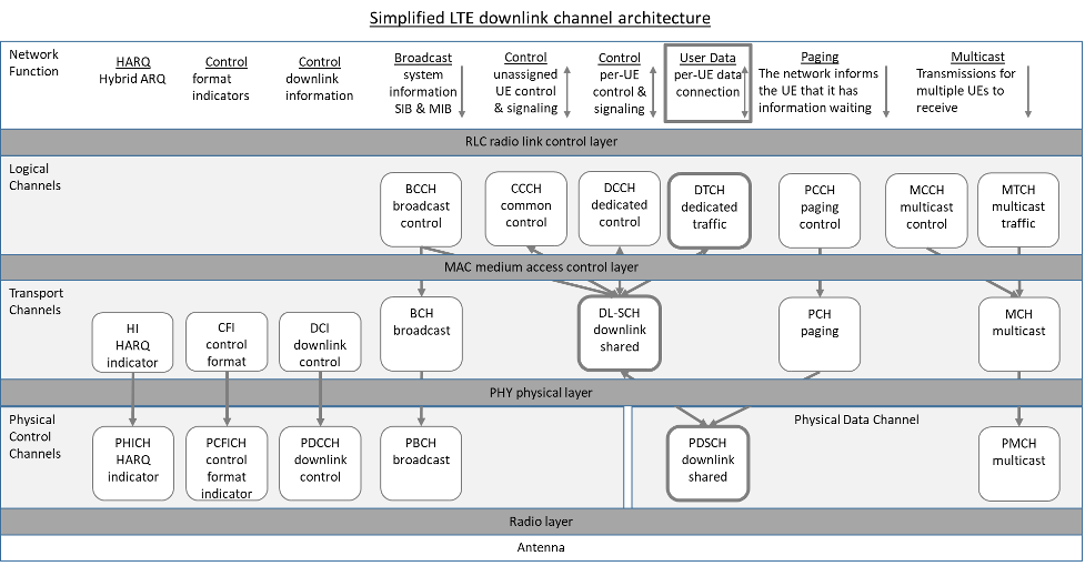
5. Control and signaling channels
Wi-Fi does not give special treatment to control traffic: Information is carried in separate packets, interleaved with data packets over the air. The traffic gains some priority from elevated QoS settings.
In CBRS, defined REs in the frame structure are designated for control traffic for uplink and downlink – they are reserved and not available for user data. Sequences of noncontiguous control REs are further structured into different control and signaling channels for designated purposes like error control, downlink and uplink control and control format indication. The use of designated channels ensures a minimum data rate for control traffic, unaffected by user data.
6. The Scheduler
CBRS has a strong frame structure, a rigid allocation of transmission opportunities to uplink and downlink, and a fraction of symbols reserved for control channels. All this is controlled by the base station, which also identifies the PRBs where each of its client devices should transmit or receive data. But in order to allocate efficiently, it needs to know what traffic each client wants to transmit, its priority and QoS sensitivity, and the available bit rate for each uplink and downlink connection.
This requires that a good deal of information on data buffer levels, channel conditions and traffic policy is brought together at a single location, the Scheduler function in the base station, which then determines the optimum allocation of PRBs in future frames, and transmits this pattern to its client devices. The Scheduler holds much of the intelligence of a CBRS system, and its algorithms are proprietary and tightly guarded by vendors. A good Scheduler will ensure that each traffic flow attains its required service level under varying network conditions and traffic profiles.
With OFDMA, Wi-Fi 6 also has a Scheduler that performs similar functions to that in CBRS, but prior to that, it used distributed mechanisms for bandwidth allocation across the network.
7. Network and cell selection
Whereas a Wi-Fi client scans for networks by listening for beacons and sending probe requests, CBRS embeds network and cell information in channels in the frame. A client device needs to synchronize to the frame to decode these values, including the operator identifier and cell site ID, and match them to values in its SIM (Subscriber Identification Module) card. Whereas the cellular network uses the PLMN (Public Land Mobile Network) identifier to find a suitable signal, CBRS distinguishes different networks by using the TAI (Tracking Area Identifier).
8. Handover
As mobile clients move across the network, they must hand over to new access points – an evolution that is difficult to control, as it often takes place under poor transmission conditions and severe time constraints. Wi-Fi engineers are familiar with the issues of handover and follow many rules of thumb in designing networks for smooth mobility.
The CBRS model has a few important differences from Wi-Fi. The most important is that it is controlled from the base station. As the client device senses a weaker signal, it starts to scan for other radios, and reports this to its base station. When a suitable handover candidate is found, the base stations coordinate to ensure it sets up PRBs to accommodate the new traffic before the client is sent a message instructing it to handover.
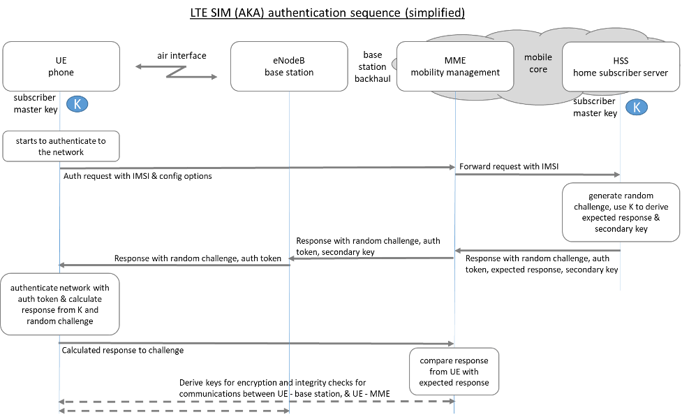
9. Authentication
Both Wi-Fi and CBRS have very secure authentication and encryption models.
Wi-Fi in enterprises uses WPA3 in 802.1X mode, supporting passwords or X.509 certificates for credentials and authenticating directly to the enterprise. However, CBRS is limited SIM authentication, where the authentication server is usually in the network provider’s cloud. Modern devices have eSIM capabilities, avoiding reliance on physical SIM cards. The authentication model of CBRS is complex and does not easily integrate with current enterprise networks.
More CBRS for Wi-Fi Experts
If you’re interested in learning more, we at Aruba have created a three-part series to cover much of what you’ll need to know to get started with CBRS:
CBRS LTE Technology for the Enterprise: The Radio
CBRS LTE Technology for the Enterprise: Signaling and Control
CBRS LTE Technology for the Enterprise: Network Implementation