This article has lots of pictures. We will be visually discussing how antenna choices indoors can affect the operation of MIMO and it more advanced cousins with 11ac which are Tx BF and MU MIMO.
If you recall from the Antennas in the Spotlight posting we talked a lot about degrees of freedom. I will show you how the use of directional antennas and steered directional antennas can have a direct negative impact on the operation of the features listed above when operating with more than 1 stream with a focus on MU-MIMO.
First: The channel
To reiterate. The channel is everything that happens between the AP and the client. All of the walls, the ceiling, the floor and all of the obstacles in the room
Second: Degrees of freedom
As discussed in the earlier blog the degrees of freedom in a space are determined by the number and power level of the reflection paths in the channel. Weak paths do not contribute to the degrees of freedom.
The number of streams that are well supported in a channel has to be the same or less than the degrees of freedom
Using directional antennas, steered or fixed, reduces the number of reflection paths illuminated which goes directly to the degrees of freedom and the number of supported streams.
While it seems intuitive that a directional antenna can increase the signal strength towards a single client, with the advent of multi-stream handsets and the continued proliferation of multi-stream tablets and PCs, the antenna choices that are available with a product can significantly impact delivered performance.
MU-MIMO further complicates this because not the targets of a transmission can be in three totally different directions. For MU MIMO to work properly all of the antenna elements have to be able to "see" all of the clients. The antenna subsystem, in concert with the chipset has to be able to peak a particular stream at a given client and NULL out the others that are sent simultaneously. The nulls cannot be created at the AP. The AP has to use the channel to create the nulls and those nulls coincide directly at the antenna on the client.
To achieve this nulling in a particular place all of the antenna elements have to send, adjusted for amplitude and phase a copy, of all streams. If you have multiple beams steered in multiple direction this is completely broken.
3: The analysis and the pictures
The Space
For the purposes of this blog we will define a space which is 20m x 20m x 7m
We will place the AP at 5m to the right and 5 m down from the center of the room and we will look at clients on a line 5 m up from the center line of the room
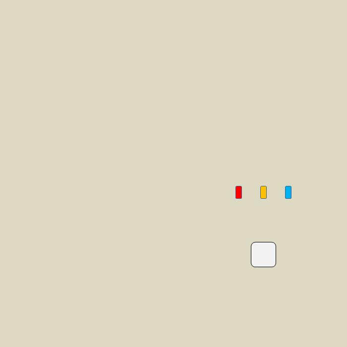
We are placing the clients on a line to simplify presentation of the data. The approach here is fully generalized.
We'll look at the electric field characteristics with 1, 5, 10, and 25 dB loss on each bounce. Then we'll focus on drywall construction where reflections from walls are typically 6 dB down. That means after 3 bounces the energy is reduced by 18 dB.
The Antennas
Case 1: 4 omni elements in a square spaced ½ wavelength apart
Case 2: 4 directional elements in a line with 90 degree beamwidths
All directionals are pointing in the same direction which gives the best result.
Impact of reflections
The ideal case for MIMO and the related features is a reflection rich environment maximizes the degrees of freedom in the channel.
Each of the plots shows a cross section of about 2.1m which is ~40 wavelengths at 5.5 GHz
This is what the fields look like with varying losses on each bounce and the AP antenna elements are in a line with a half wavelength between each.
As can be seen in the plots as the loss on the bounce increases the variations of the field decreases. This makes it more difficult for MIMO, Tx BF, and MU MIMO to work for multi stream operation.
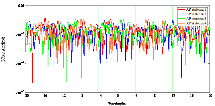
Fields from each of the AP antennas with 1 dB loss on wall bounces
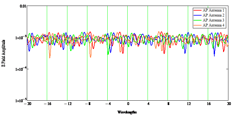
Fields from each of the AP antennas with 5 dB loss on wall bounces
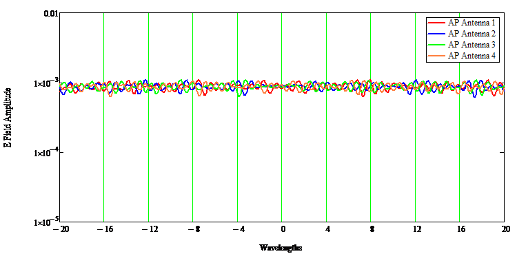
Fields from each of the AP antennas with 10 dB loss on wall bounces
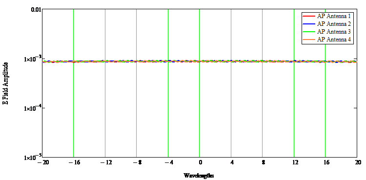
Fields from each of the AP antennas with 25 dB loss on wall bounces
Impact of reflections and directional antennas
The ideal case for MIMO and the related features is a reflection rich environment maximizes the degrees of freedom in the channel.
Each of the plots shows a cross section of about 2.1m which is ~40 wavelengths at 5.5 GHz
This is what the fields look like when the varying losses on each bounce and the AP antenna elements are in a line with a half wavelength between each and an antenna pattern with 90 degree vertical and horizontal beamwidths:
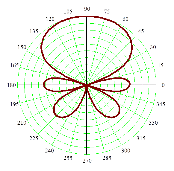
Antenna element pattern used for directional simulations. 3 dB per division.
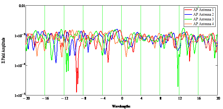
Fields from each of the AP directional antennas with 1 dB loss on wall bounces
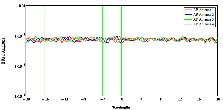
Fields from each of the AP directional antennas with 5 dB loss on wall bounces
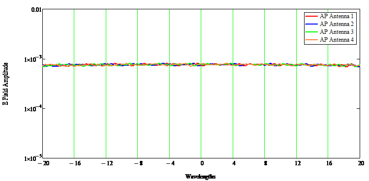
Fields from each of the AP directional antennas with 10 dB loss on wall bounces
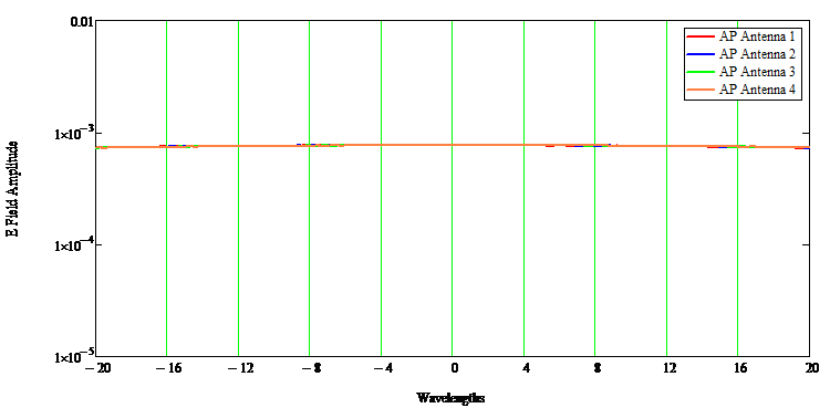
Fields from each of the AP directional antennas with 25 dB loss on wall bounces
From the above we can see that the directional antennas substantially reduce the amplitude and frequency of the ripples for each of the cases simulated. Therefore, as expected the use of directional antennas, the apparent reduction will negatively impact the support of MIMO, Tx BF, and MU MIMO
Direct Comparison in Room with Drywall
Case 1: 4 Omnis in a Square
So let's look at a particular case now. Standard drywall give reflections at ~6 dB down.
We will now look in more detail in a drywalled space.
First with omnis on the AP arranged in a square with sides about ½ wavelength across. Here is the plot showing the fields in the area of the clients. 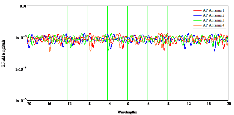
After MIMO processing here is the field plot of stream 1 at the same location. The blue dots show the location of 3 single stream clients. Note that the MU-MIMO processing has left nulls under clients 2 and 3 and the plot has been normalized to 1 where client 1 is. A well behaved system has relatively even amplitudes on the peaks
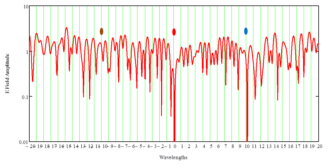
Here are the patterns for each stream
There are noticeable differences in the patterns and this in turn shows good separation of the streams mathematically. This indicates a much higher probability in proper decoding of the three streams for MU MIMO.
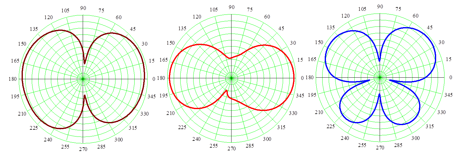
It is interesting to note that the optimum result actually moves the peak gain away from the client locations which in this case is straight up. This makes sense as the system has to cancel unwanted streams so it reduces the peak towards the client and reinforces the reflections so that the amplitudes are similar.
Case 1: 4 Directionals in a line
Now let's do this for the directional case with the same reflection conditions
As before, here are the fields from the AP before MIMO processing. Aside from the antenna change all else is held constant.
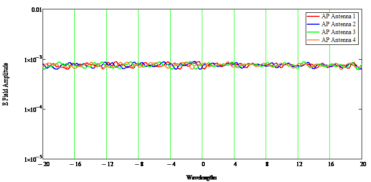
Here are the fields for stream 1 after MU MIMO processing.
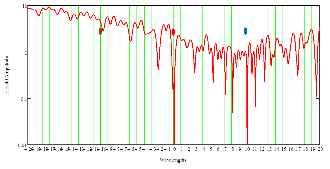
This is actually showing that the MU processing is having a difficult time converging. Client 1, as before, is located at the -10 wavelength position and the amplitude there should be normalized to 1. The math is trying to reach down to that point but since it cannot this indicates a failure of the math to converge.
And here are the patterns. 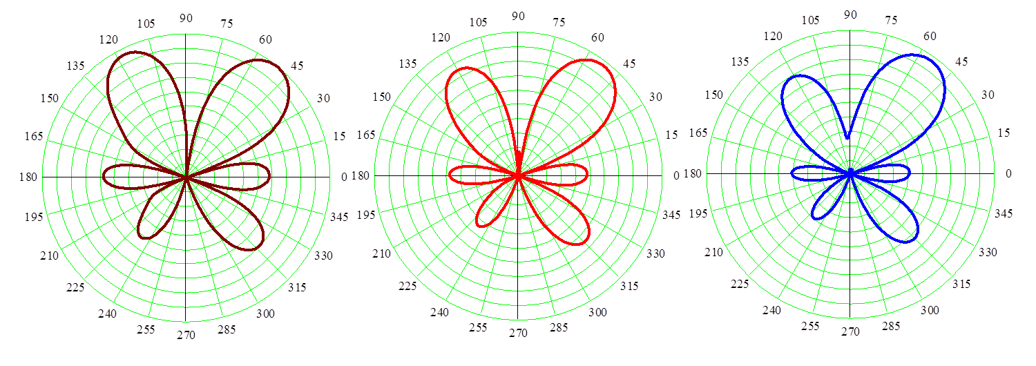
Unlike the arrangement of the 4 omnis all three patterns are very similar. This implies that the ability to decode the 3 streams is going to be much more difficult and any errors will be amplified. MU MIMO processing will have a more difficult time to support multiple streams/clients
Summary:
As discussed in previous articles the choice of antenna element can significantly impact the operation of MIMO, Tx BF and MU MIMO. Even using relative wide directional elements has a deleterious impact on the operation of these advanced features when supporting more than 1 stream.
In short, directional antennas, whether fixed or steered should not be used for systems that expects MU MIMO to operate.
@ej_wireless
Eric Johnson is director of product management at Aruba, a Hewlett Packard Enterprise company.


