By Andrea Mauro, contributor
What is a network topology?
Network topology is the arrangement of the different network elements of a communication network, usually represented with a graph.
Network topology is an application of graph theory in which different network devices are modeled as nodes and the connections between the devices are modeled as links or lines between the nodes.
There are usually two different types of network topologies:
- Physical network topology is the placement of the various components of a network and the different connectors usually represent the physical network cables, and the nodes usually represent the physical network devices (like switches).
- Logical network topology illustrates, at a higher level, how data flows within a network.
Usually, in campus LAN topologies, focusing at layer 2 (at the switching layer), structured, multi-tier models are used to simplify the design and the network implementation.
The hierarchical internetworking model is a three-layer network topology that divides enterprise networks into three layers:
- Core, composed by the highest-speed switches, with high resiliency and usually routing and other high-level functions.
- Distribution or aggregation, composed by high-speed switches with redundancy and availability.
- Access, composed of switches to which the client devices are connected.
There are also other models, for example a simplified two-layer collapsed-core model (with only core and access layers, mostly used in the SMB segment) or also other types of models like the leaf-spine model, which focuses more on cloud computing or data center environments.
Anyway, the terms core, distribution/aggregation and access are so commonly used, that the switches are usually classified for their intended purpose. For example, see the HPE Aruba Networking CX Switch portfolio.
Let’s consider a common logical topology of a three-layer model:
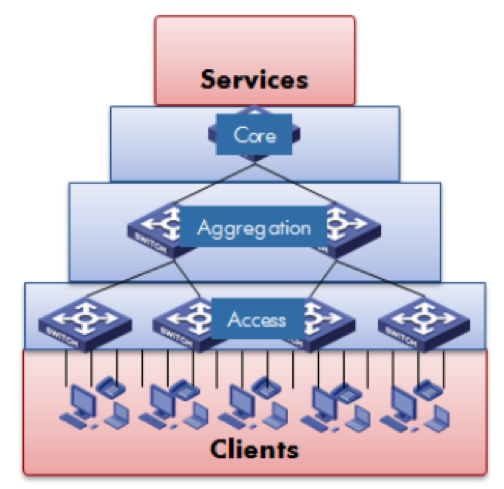
Three-layer hierarchical layer 2 topology
This can be potentially translated into a physical topology, as a non-redundant solution, where each node is just a single switch and the switches in each layer have a single link to switches in the adjacent layers.
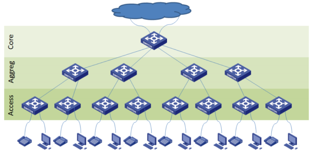
Non-redundant 3-tier LAN
That appears to be a weak solution, doesn’t it? It could be, but switches in each layer can have internal redundancy, such as redundant management, fabric and power. This can provide a reasonable amount of redundancy. For example, the core node could be a modular switch (like the HPE Aruba Networking 8400 model.)
More physical links can also be used and aggregated in link aggregation (LAG or LACP logical link) to improve resiliency and bandwidth.
A better, more preferable approach is to design the physical topology with full redundancy and fault tolerance at the core and aggregation level.
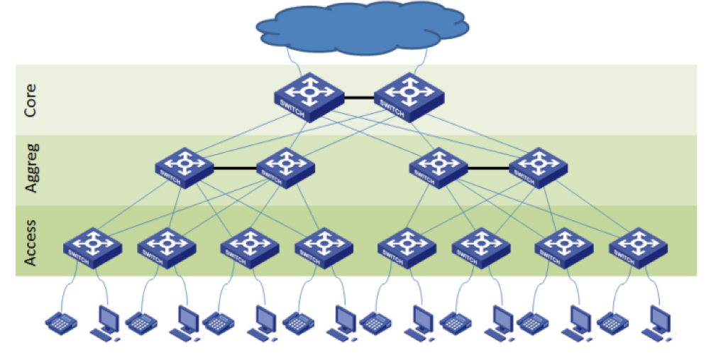
Redundant core and aggregation layer
This model is widely used because of its resiliency, but can it also provide more performance and bandwidth? Having multiple links and paths does not necessarily mean more throughput!
At least it does not on a layer 2 network, because of the limitation of the IEEE 802.3 family (the standard version of Ethernet protocols) where no loop is supported due to the lack of a layer 2 Time to Live (TTL).
This means that the real physical topology must become a hierarchical graph with no loop at all.
To achieve this goal there are two main options:
- The first is moving again to a physical topology without redundancy (as in the first diagram) and improve the resiliency using modular switches, stacking switches or independent switches in a virtual chassis configuration. Note that HPE Aruba Networking switches give you all those options depending on the model and the usage (for example the CX 83xx series supports virtualization with VSX clusters, the CX 6400 and CX 84xx series are modular, and the 6200 and 6300 series support VSF stacking).
- The second option is to use the Spanning Tree Protocol (STP) to deactivate some physical links. This means that the network fabric is not completely used and that some links will be on standby to prevent loops. Also some switches may be not normally used. Using multiple STP (802.1s), one for each different VLAN, could make the infrastructure more utilized, but can be also more complex.
Depending on your switches and your needs, you can choose one option or another.
The first option may be a little more costly, because you may need specific stacking modules, you may are lose some switch ports, or you may need to buy modular switches.
The second option may be more complex from a design perspective, bring possible issues (especially in troubleshooting) and be less efficient.
SMBs usually use a simplified two-layer model and for the core layer use a stacked or modular solution.
Leaf-spine network topology
The leaf-spine topology is a special case of a two-layer model, designed to build fast, predictable, scalable and efficient data center network infrastructure.
The main difference between the previous topology is the spine level, where there are more independent switches that are more scalable. The switches on the spine level are not connected each other:
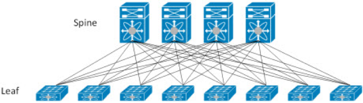
Leaf-spine network topology
Another big difference is that the leaf-spine topology is natively a layer 3 network that uses layer 3 routing and each node is a router. Usually, all routes are configured in an active state through the use of Equal-Cost Multipath (ECMP) to have all links active.
So, the first big problem with this topology is how stretch layer 2 networks (usually the different VLANs) on a layer 3 network? Network virtualization and protocols like VxLAN can help in this goal.
Another aspect is how match this topology in a physical topology? Can it be done 1:1? Depending on your type of network and level, maybe. In some cases, each leaf node represents a couple of physical switches (usually the top-of-rack switches) configured to be a single logical switch (with stacking or virtual chassis features).
The leaf-spine topology is not really used in the SMB market.
Auto-Discover Network Topologies
There are some tools and protocols that are useful to build your network topology.
In most cases those tools are used in the Wi-Fi network to simplify the deployment and configuration.
But there are also some interesting options for the wired LAN. For example, Link Layer Discovery Protocol (LLDP) is a vendor-neutral link layer protocol used by network devices for advertising their identity, capabilities and neighbors on a local area network based on IEEE 802 technology, specifically 802.1AB. This permits automatically discovery and advertising of the node neighbors.
Several tools use this protocol to automatically build the network topology. For example, in HPE Aruba Networking Central, the topology map provides a graphical representation of the network layout, details of the devices deployed in a branch site, and the health of the links.